| DESIGN
I was first intrigued by
the look of a Quest Rocket Aurora T3 when browsing the Net for just another
kit to build. Totally bored with big kits out of the bag - I look to the
challenge of an up-scale. Having failed miserably at a club launch in boost
glider competition - the Aurora T3 looked like a glider possibility. Not
long before I gave up the idea of glider competition - the upscale idea
hit.
 The
kit was purchased from Value Land and
arrived in great shape like all their deliveries. I gotta say it
because everything is individually bubble wrapped. Inspection of
the kit showed all parts in the bag and whole. The
kit was purchased from Value Land and
arrived in great shape like all their deliveries. I gotta say it
because everything is individually bubble wrapped. Inspection of
the kit showed all parts in the bag and whole.
I went straight for the glider
parts to make sure this was do-able at the scale I wanted. I simply
laid out the laser cut balsa parts and traced them on graph paper.
Next I had Kelli at my work scan in the page and she factored it up for
the plotter. It was pretty much a 4:1 ratio coming in at 4.05% enlargement.
The upscale plotted dimensions work well with the available parts on the
market now.
For actual construction of
the rocket I generally plan to follow the kit instructions concerning dimensions
and placement of parts allowing for the upscale ratio.
SIMULATION
To make sure that upscale
Aurora 4.0 would fly well, I had to first build the model in RocSim.
I measured all parts of the Quest kit and using the supplied kit instruction
sheet, upscale the placement dimensions of parts. The problem with RocSim
3.0 is designing any parts to attach to the exterior much less design a
glider. I simply tried to add more parallel fins to replicate the surface
area of the glider. In a later construction step I will weigh the
rocket to balance the real weight of the rocket and the glider in design
simulation. A test throw of the glider will be necessary to trim
it for flight.
PIECES and PARTS
/ GLUE
Parts used in construction
of the Aurora 4.0:
BOOSTER
| Nose Cone |
LOC 3.9" |
| Payload |
None |
| Body Tube |
PML 3.9", 48"
length |
| Fins |
(3) 3/16" birch
4 ply |
| Motor Mount |
38 mm LOC paper, 17"
length |
| Centering Rings |
(3) 3.9" 3/16" plywood,
38mm |
| Motor Retention |
(2) 10/32" bolts,
T-nuts and screen clips |
| Shock cord |
(1) 1" tubular nylon
20' w/ loops |
| Recovery |
PML 54" round chute |
GLIDER
| Nose Cone |
BMS
BNC70AJ Alpha Classic |
| Body Tube |
LOC 54 mm, 24.3" length |
| Wings/ Stabilizers |
2 sheets popular 3/32"
12"x24" with
3/4 oz fiberglass
one layer |
| Bulkheads |
BMS
BT-70 Nose Blocks |
| Altimeter |
Olsen - M2,
400' main |
| Shock cord |
Tubular nylon 1/2"
10 foot |
| Recovery |
Top Flight 36" round
chute |
| Motor Can |
24 mm motor tube and
centering rings |
COMING TOGETHER
Glider Assembly
The first construction activity
was the sizing and cutting of the glider parts. I used 3/32" 12"x24"
popular sheets for the wing parts. Cutting the parts was easy using a utility
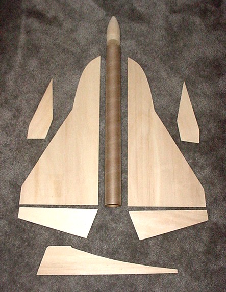
knife, straight edge and the template developed above. The nose cone
is balsa and I ordered it from Balsa
Machine Service. It is a BNC70AJ and fits a BT-70, sand the shoulder
lightly and it fits a 54 mm body tube. For added durability I lightly
coated the cone with finish epoxy and sanded. Figure 1.
My biggest fear was the wing
span of the glider not fitting on one sheet of material. As luck
would have it each wing fits the 4.0 ratio and works great with the 3/32"
12"x24" popular sheets available locally at MRS Hobbies. Carefully laying
out the templates I was able to use only two sheets for all the glider
wing parts. Test fitting the parts together revealed not stray edges. I
fretted in getting this joint right as the wings were slightly warped.
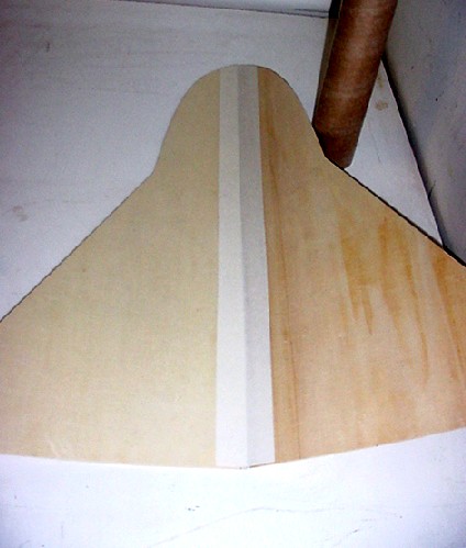
I had pressed the wings for a while and had to go for it. The best idea
was to use two sided fiberglass carpet tape. The tape would provide
an instant bond and hold while epoxy sets. Critical to the joint is also
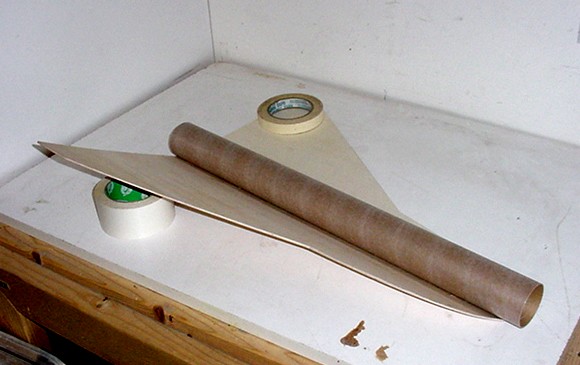
the angle of the wings. A ten degree angle from plane for both wings was
necessary. Center the glider body tube and there you have the beginning
of the Aurora 4.0 glider. Figures 2 and 3.
Figure 4, shows the addition
of the top and bottom stabilizers. Before placing the bottom stabilizer,
I cut a groove, the width of the stabilizer, along the joint seam. Before
adding the bottom stabilizer I laid a single layer of 3/4 oz. fiberglass
and added the bottom stabilizer on top of the glass. This added just enough
rigidity to the wing surface to hopefully protect it in landing.
A layer of 3/4 oz. glass was also added to the bottom stabilizer.
 |
 |
 |
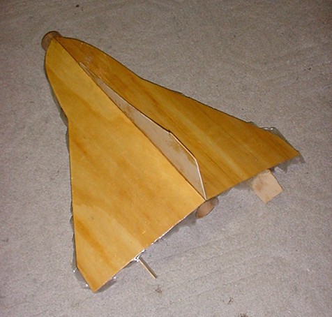 |
Figure 1
Parts |
Figure 2
Glass tape joint |
Figure 3
Body Tube |
Figure 4
Glass bottom surface |
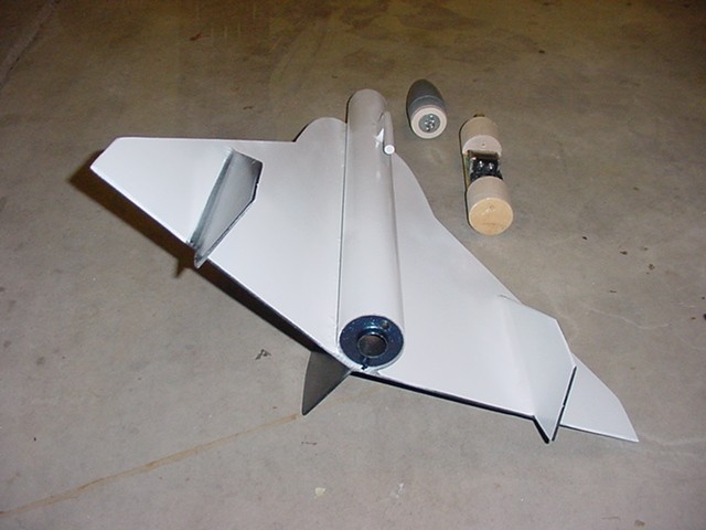
Packed inside the glider
will be an altimeter bay, recovery parachute and 24 mm motor mount.
Why all this if it is glider recovery? Well In the interest of public
safety - I am designing the glider for glide descent with an altimeter
controlled chute recovery during the final approach. Additionally
for balance and realism on the glider, I am adding a 24 mm motor mount
to hold an Aerotech 24/40 rms motor with just a delay charge. The delay
charge, ignited at apogee, will hopefully discharge tracking smoke to aid
in spotting the glider. Figure 5
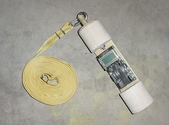
Critical to the recovery
portion of the glider is the altimeter bay construction. To keep
weight down I halved a BT-70 balsa nose block from Balsa
Machine Service and crafted an altimeter mounting board in between.
Wiring tunnels were drilled forward and aft on the blocks to pass through
e-match leads from the the altimeter to ejection charge and delay charges.
The altimeter bay will be screwed into place inside the glider body tube
prior to launch. Figure 6.
The most complicated construction
of the glider has been the attachment of the rear flaps. I toyed
with using the fiberglass tape again, however it is two sided and did not
want the upside sticky. After yet anther trip to MRS Hobbies, I obtained
aileron control tower, connector rods and wing hinges from the RC airplane
part selection. The intent is to have a sturdy flap that can be modified.
Figure 7.
 |
 |
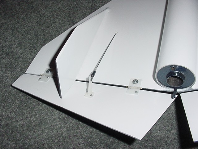 |
Figure 5
Glider Rear |
Figure 6
Glider Altimeter
Bay |
Figure 7
Glider Flap Assembly |
Booster Assembly
Several tries of painting
the nose cone on the booster with light sanding and repeated paint and
sand brings a great smooth paint finish. Epoxied into the cone is
a 1/4"x 4" eyebolt. The assembly seems sturdy, but will also loop kevlar
thread into the bolt using the normal cord attachment eyes holes on the
cone.
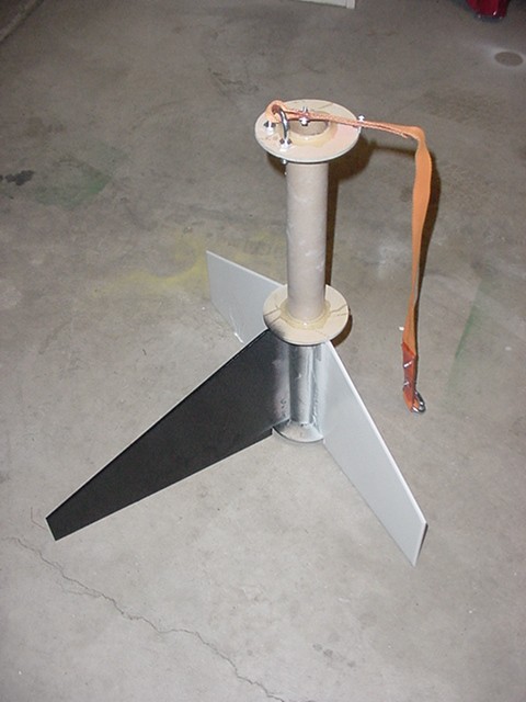
The motor mount is a LOC
38 mm paper tube 17" in length. Three 3/16" plywood centering rings are
added to create the fin can assembly. A PML 3.9" diameter by 48"
length tube is utilized for the booster body. Ron Weigel at Rocky
Mountain Rocketry was the source for cutting the centering rings and
slotting the body tube. The fins are upscale from the Quest Aurora
kit pattern. I cut the fins from 3/16" plywood. One exception is
the outboard or center fin. I intentionally added 20% more surface
area to the fin to offset the glider surface area which would hang on the
opposing side of the booster. The intent is to equalize the drag and provide
best as possible vertical launch. A U bolt is added to the forward centering
ring for connection of a 24" bridle. The bridle is 1" tubular nylon cord
looped at both ends. A kevlar cord sheath will cover the bridle.
I made the bridle because I can't reach down the 4' body tube to connect
a reusable shock cord each time for flight. Figure 7. The body
of the booster is simple. No payload section - just fin can, body
tube and nose cone. Total length five feet. Figure 8.
 |
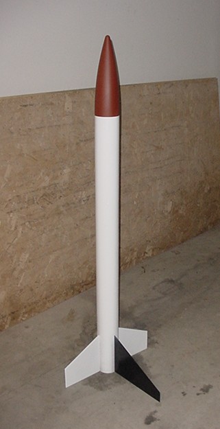 |
Figure 7
Booster Fin Can |
Figure 8
Booster |
Final flight worthy construction
will be completed within hours of the beginning of the HellFire 7 Launch
September 14-16, 2001 hosted by the Utah Rocket Club, UROC.
FLIGHT
Planned flight will
be with a I-154J-6. It should loft to about 1,500' feet and detach the
glider at apogee. The booster will deploy only a main chute and return
under a 54" canopy. The altimeter on board the glider should fire
an e-match in the glider mounted motor casing to ignite an inverted Estes
D12-0 motor to create tracking smoke as the glider returns.. The glider
will trim out and at 150' deploy a 54" recovery chute to eliminate the
possibility of spectator or property damage.
Ready for flight at the October
2001 UROC launch.
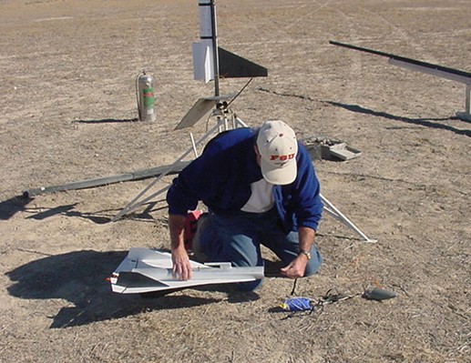
Simple prep and load of
the motor and chute in the booster. The arming of the altimeter and final
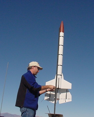
chute packing of the glider has to be accomplished at the pad. Figure 9.
Double check the installation of the igniter wire and give the OK to launch.
Figure 10. Flight Ready Figure 11.
 |
 |
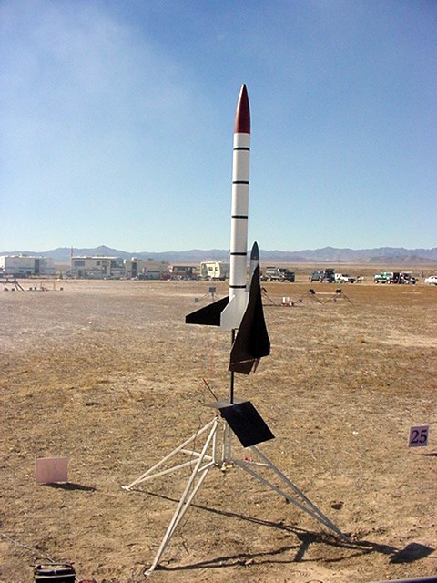 |
Figure 9
Arm Glider |
Figure 10
Launch Prep |
Figure 11
Flight Ready |
The actual flight was good
at lift off. The Aerotech I154J caused he lift off to be slow and easy.
The rocket rose and rotated over on the glider side. It continued
to climb and arc northwest. No delay charge was noticed at apogee
to pop the main chute or detach the glider. The D12-0 in the glider
did ignite and provide tracking smoke as the rocket AND glider nosed in.
The altimeter charge in the glider did blow and release the glider chute.
On the ground the main delay charge did blow. The motor 6 sec. delay
was more like a 12 sec.
Oh to rebuild - many discussions
were held as to a fix. Stay tuned.
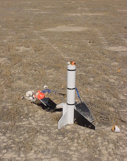 |
Figure 12
Smoked Glider |
|