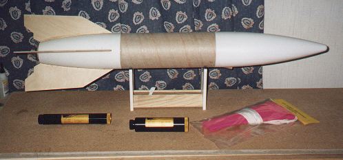
Bob Fortune's
V2 scratch build & plans |
Lost one November day in
the web world, and looking for a kit to kick with, I found a scratch build
article about a 4"
V2. I was held by the simplicity of the proposed construction.
It seemed simple enough that all I had to do was make a few cuts and glue
it together. But on the other hand I wanted to push the design a little.
How could I make this into a dual deployment with an altimeter bay? In
essence it became a design build project. I call it 2-V-2. I had a few
parts lying around and ordered what parts I thought I needed right away.
I picked up two LOC 4" nose
cones, 38 mm centering rings, 3/16" 4 ply birch plywood, and two 4" dia
paper tubes cut to 6" lengths. First construction step was to glass the
body tubes with two wraps of 2 oz. SIG fiberglass. Then I cut the
fins and cut the tail cone and the nose cone. Built the Altimeter bay and
finally, assembled the rocket. Easy as igniter wire laced thermalite eh.
Follow my construction below.
|
CONSTRUCTION
|
|
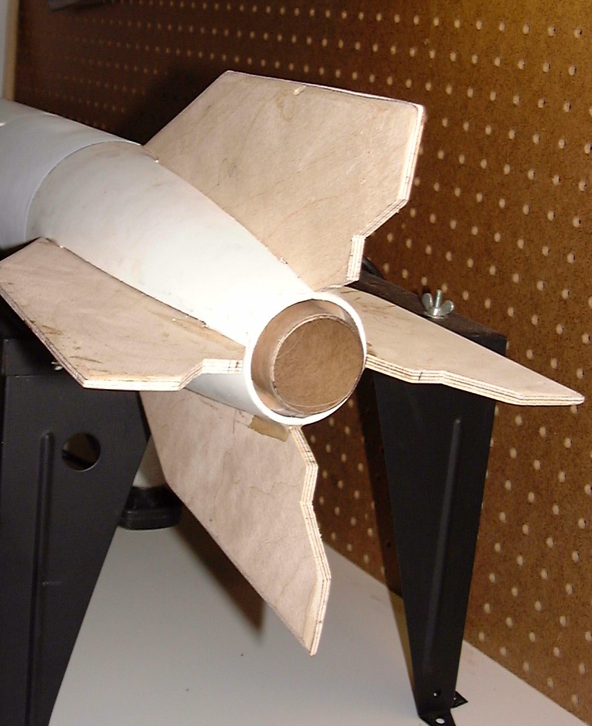
Fin Can 38 mm Motor
Mount |
Tail cone and 38 mm Mount:
It sounds easy - just cut
off about two inches off the top of one LOC 4" nose cone. Use a piece of
54 mm motor tube as a marking guide. Slip the motor tube over the nose
and trace around the edge. Viola a 54 mm opening. The hard part is actually
doing the cut. HACK. I traced the line with a pen knife first, and then
scored the cut deeper with a hacksaw. Save the clipped nose piece for the
shock cord mount. Also, cut off the shock cord mount side of the cone leaving
only 1 1/4" of the shoulder.
|
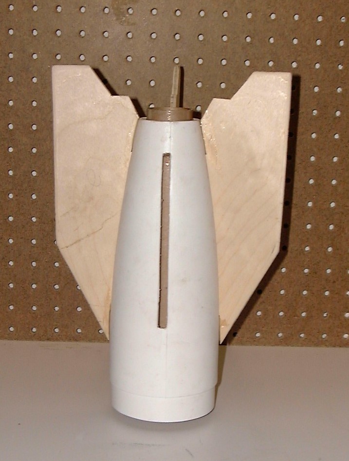
Fin Can |
Tail cone and 38 mm Mount:
Since I was now a pro at
cone cutting I turned to cutting the other LOC 4" cone for the fins. Cut
the fins first to make sure the fins match the tail cone cuts. The original
V2 article includes fin templates and a template to the wall cut. I used
the fin and traced it onto the tail cone instead. I used 3/16" 4 ply birch
plywood for the fins.. I traced the fin outline and cut the fins on my
trusty router / jigsaw table. Cut the 38 mm motor tube to 11 inches. Enough
for over hang at the top and bottom of the tail cone..
|
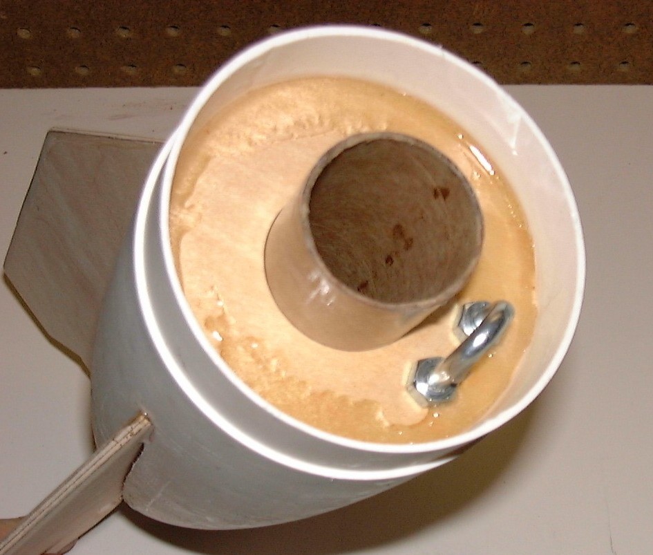
Top of Fin Can |
Recessed Area in Tail
cone:
The motor mount and fin can
are one in this model. No building the mount and then insert into the rear.
I used two old rings lying around to make this mount. First I sanded a
1/8" 2.56" 29 mm ring into a 2.5" 38mm ring. Then I sanded a 3.9" ring
down a little to just fit inside the lip of the fin can. The rings are
spaced to just fit the fin edge and to make contact with the motor tube.
(The lip is the area just inside the cut off shock cord mount.) This created
a recessed area in the fin can of about an inch. All the more room
for cord and chute. Add in a "u" bolt and there you have it.
|
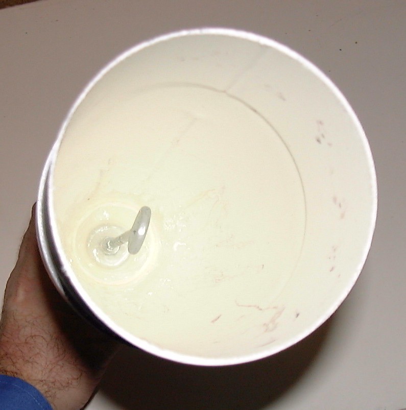
Nose Cone / Eye Bolt |
Nose Cone and Shock Cord
Mount:
Using a LOC 4" nose cone,
cut off the existing shock cord mounting area. Leave at least a 3" shoulder
on the cone. hen use the 2" long nose portion clipped off earlier - run
a 1/4" x 8" eye bolt through the old piece and secured it with washers
and nuts. Next, rough up the forward end inside of the nose cone with a
rasp. Epoxy the eye bolt assembly into the forward end of the nose cone.
The assembly provides extra mass in the cone typically needed with a V2
and it provides space necessary for the main parachute in the payload compartment.
|
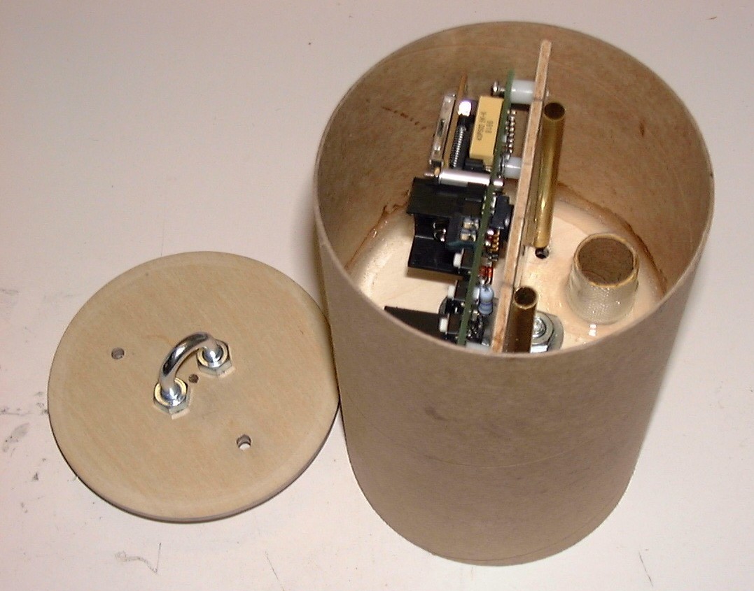
Bottom view of Altimeter
Bay
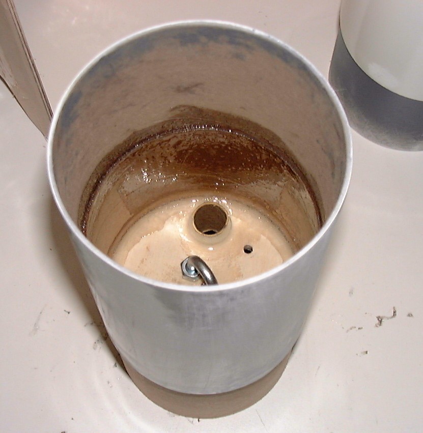
Top View of Altimeter
Bay
in Payload Section
|
Altimeter Bay:
This was the whole trick
to the project. I decided early on I wanted to do this as a dual deployment
rocket. The problem being space. I somehow had to retain a 12" body tube
length. So I crafted a 3" altimeter bay in a 6" paper tube coupler by laying
the altimeter on its side. I am using an Olsen M2 altimeter which has a
barometric G switch and not mechanical launch detection. It is sized just
right to mount and lay on its side. Also, instead of mounting the ejection
can exterior to the can I am mounting it opposite the altimeter. I epoxied
in an 18 mm motor tube to hold a Blacksky safe eject can. I would like
to add a remote safe switch. Assembling the bay I will use thin dense foam
strips to help seal off between the altimeter mounting board and the eject
can area. ( In the photo at left the eject can will mount in from this
side and protrude down out into the payload half).
Construction was with a 6"
paper coupler. Mount half way in the coupler a 3/16" bulk head cut for
the inside of a coupler. That will be the top of the bay. The bottom was
crafted gluing a 1/8"x3.9" bulk head plate (cut for the inside of a coupler)
to another 1/8"x3.9" bulk head plate. This will be the bottom of the bay.
Add U bolts, two all thread connecting rods, and top with wing nuts.
Note the photos at left.
The upper photo is the coupler upside down. The bulk head plate is only
half way in the coupler. The second photo shows the payload section right-side-up.
The payload body tube added on. There is 2 3/4" depth in the payload section
down to the coupler plus the 3" of coupler to the bulk plate.. The nose
cone shoulder has been cut to match the 2 3/4" depth.
|
| Other Pics |
|
 |
 |
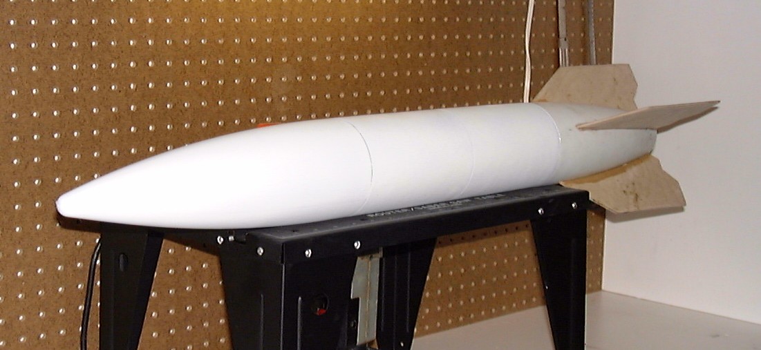 |
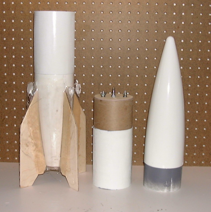
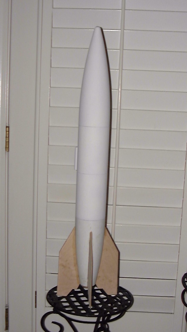
Final paint is on.
Wow! I am tired of sanding and painting. The scratch built altimeter bay
is also now ready. A trip to Radio Shack provided me with a speaker
terminal block and the connection for the powder keg. I also added an on/off
push button for the altimeter to mount internally and can now activate
the altimeter on the pad through the air pressure hole.
It is a tight package - but
that is the design!
Total weight with chute,
cords, protectors, quick links and altimeter is 54 oz.
5/21/01 |
| 4/20/01 |
|
FLIGHT HISTORY
|
|
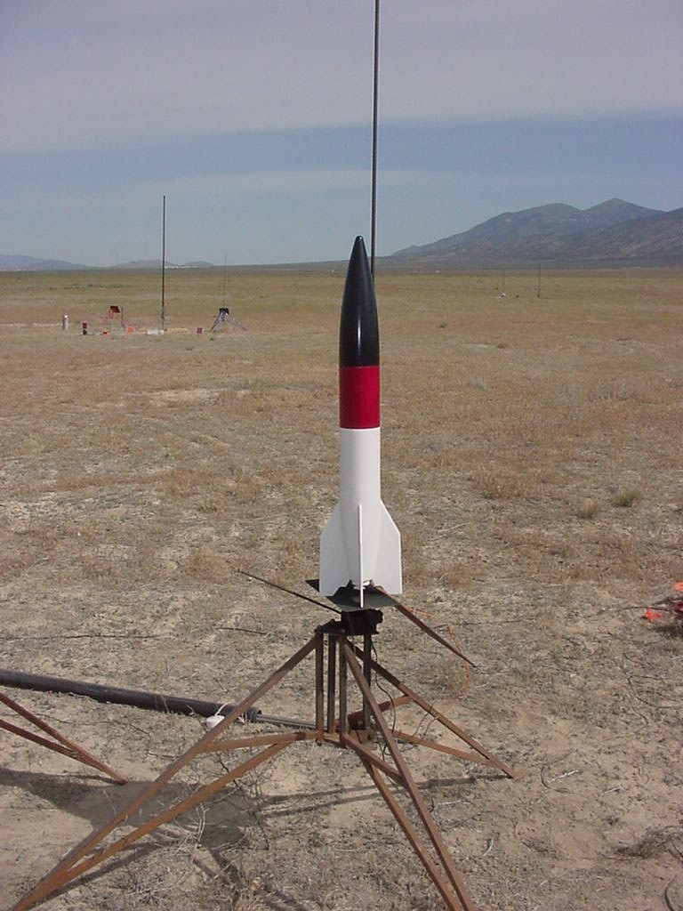
| FIRST FLIGHT:
Day two of the National Sport
Launch NSL2001.
I loaded a Dr. Rocket 38/600
case with an I-284w-14. This motor will really power the rocket up.
next I loaded a BlackSky Easy Eject Canister with an igniter wire and 1.5
grams of 4f. Setting these aside I set the Olsen altimeter for the flight.
The Olsen works great in this situation as I have turned the altimeter
on its side to fit in the 3" deep altimeter bay. I programmed the unit
to activate upon barometric pressure change instead of "g" switch.
Attach all parts together and load the 30" drouge and 45" main chutes,
cords and altimeter bay. Ready to launch.
|
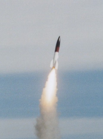
As of May 2001,
the 2-V-2 has flown three
times.
Twice on Aerotech I-284
and once on an Aerotech
I-211.
|
|
|
|
Click
here to load and view the
"mpg"
video of the take-off
|
| Flight and recovery
was predictable. The rocket did weather cock northeast into the wind more
than I would have liked. May need more nose weight next time. The rocket
also warbled a little at lift off as evidenced in the video. Overall,
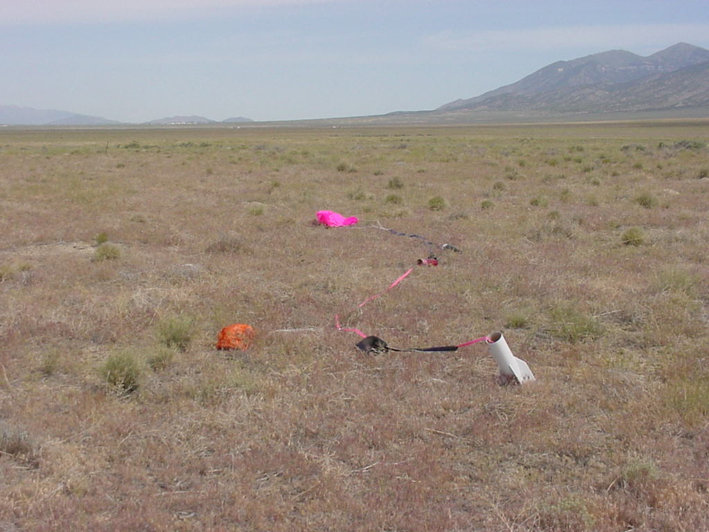
a good flight. The main eject charge was set for 850'. The main chute
opened and a soft landing was had. The altimeter reported 3,632'
I has hoped for a higher straighter flight and an altitude of around 4,000'. |
|